How to Precisely Connect Light Chips to Optical Fibers
This patent describes a clever way to accurately align tiny light-emitting components inside a photonic chip with an external optical connector, using a built-in alignment mark and a viewing hole.
Original patent title: “Optical and thermal interface for photonic integrated circuits”
This patent describes a clever way to accurately align tiny light-emitting components inside a photonic chip with an external optical connector, using a built-in alignment mark and a viewing hole. Granted to Aurrion in 2021 with 22 claims and 1 forward citation, and it is expected to expire in 2040.
Coverage
What does this patent actually cover?
This patent describes an optical apparatus that precisely connects a photonic integrated circuit (PIC) to an optical interface unit. The PIC has a light emitter that sends light through its material to the optical interface unit, which is attached to the PIC's bottom side (claimclaimA numbered sentence at the end of a patent that legally defines what the inventor owns. The most important section.Read more → 1). To ensure perfect alignment, the PIC includes a special "alignment feature" on its top side, which is built at a known, fixed distance from the light emitter (claim 1). A small "hole" extends from the top side of the PIC down to the bottom, allowing a clear view of this alignment feature from the same side where the optical interface unit connects (claim 1). This setup allows for very accurate positioning of the optical interface unit relative to the light emitter. For example, when manufacturing, a camera could look through the hole to see the alignment feature and then precisely place the optical interface unit based on its known offset from the light emitter. The patent also mentions a heat spreader layer around the optical interface unit to manage heat (claim 10).
The gap
What does this patent NOT cover?
- Does not cover alignment methods where the alignment feature is not offset by a predetermined distance from the light emitter (claimclaimA numbered sentence at the end of a patent that legally defines what the inventor owns. The most important section.Read more → 1).
- Does not cover systems where the alignment feature is viewed from the same side as the light emitter, rather than through a hole from the opposite side (claimclaimA numbered sentence at the end of a patent that legally defines what the inventor owns. The most important section.Read more → 1).
- Does not cover optical apparatuses that lack a hole extending from the first side to provide a line of sight to the alignment feature (claimclaimA numbered sentence at the end of a patent that legally defines what the inventor owns. The most important section.Read more → 1).
- Does not cover systems where the optical interface unit is not connected to the second side of the photonic integrated circuit (claimclaimA numbered sentence at the end of a patent that legally defines what the inventor owns. The most important section.Read more → 1).
- Does not cover alignment techniques that do not involve a heat spreader layer surrounding the optical interface unit (claimclaimA numbered sentence at the end of a patent that legally defines what the inventor owns. The most important section.Read more → 10).
These exclusions are unique to PatentBrief — derived from the actual claim language, not patent-office boilerplate.
Key facts
What made this novel
The noveltynoveltyThe requirement that an invention be different from anything publicly known before its priority date.Read more → lies in creating an alignment feature directly on the PIC's top surface, offset by a precise, predetermined distance from the light emitter, and then providing a viewing hole through the PIC to see this feature from the bottom. This allows for highly accurate, "self-referenced" alignment during assembly, even when the light emitter itself is hidden.
The Patent Drawing
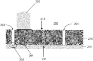
Schematic visualization of the patent's claim structure. Hand-drawn diagrams in progress for each landmark patent.
Where you've seen this
Real-world examples
High-speed optical transceivers in data centers
Fiber optic communication modules
Lidar systems for autonomous vehicles
Optical sensors for medical diagnostics
Quantum computing interconnects
Why it matters
The bigger picture
Photonic integrated circuits are crucial for high-speed data communication, sensing, and computing. Accurately connecting these tiny light-based chips to external optical fibers or lenses is a significant manufacturing challenge. This patent addresses that by providing a robust, repeatable method for precise alignment and thermal management, which is essential for reliable and high-performance photonic systems. This precision helps reduce signal loss and improve the efficiency of light transmission, impacting industries relying on optical data transfer.
Filed
March 9, 2020
Granted
October 19, 2021
Market context
Who's building on this
Companies in this space
Companies like Aurrion (the assigneeassigneeThe entity that owns the patent — usually the inventor's employer or a company.Read more →, now part of Juniper Networks) and other major players in optical networking and silicon photonics, such as Intel, Broadcom, and Cisco, are actively developing and integrating photonic integrated circuits. Startups focusing on advanced optical interconnects for AI/ML accelerators also rely on precise packaging techniques.
Market impact
This type of precision alignment and thermal management technology is crucial for improving the performance and reliability of photonic integrated circuits. It enables higher data rates and lower power consumption in optical transceivers, which are fundamental components in data centers and telecommunication networks. By simplifying the manufacturing process for complex optical assemblies, it helps reduce costs and accelerate the adoption of silicon photonics in various applications, from cloud infrastructure to advanced sensing.
Claim 1 — Plain English
What this patent covers
This patent describes an optical apparatus that precisely connects a photonic integrated circuit (PIC) to an optical interface unit. The PIC has a light emitter that sends light through its material to the optical interface unit, which is attached to the PIC's bottom side (claim 1). To ensure perfect alignment, the PIC includes a special "alignment feature" on its top side, which is built at a known, fixed distance from the light emitter (claim 1). A small "hole" extends from the top side of the PIC down to the bottom, allowing a clear view of this alignment feature from the same side where the optical interface unit connects (claim 1). This setup allows for very accurate positioning of the optical interface unit relative to the light emitter. For example, when manufacturing, a camera could look through the hole to see the alignment feature and then precisely place the optical interface unit based on its known offset from the light emitter. The patent also mentions a heat spreader layer around the optical interface unit to manage heat (claim 10).
The clever bit
The novelty lies in creating an alignment feature directly on the PIC's top surface, offset by a precise, predetermined distance from the light emitter, and then providing a viewing hole through the PIC to see this feature from the bottom. This allows for highly accurate, "self-referenced" alignment during assembly, even when the light emitter itself is hidden.
What it does not cover
- Does not cover alignment methods where the alignment feature is not offset by a predetermined distance from the light emitter (claim 1).
- Does not cover systems where the alignment feature is viewed from the same side as the light emitter, rather than through a hole from the opposite side (claim 1).
- Does not cover optical apparatuses that lack a hole extending from the first side to provide a line of sight to the alignment feature (claim 1).
- Does not cover systems where the optical interface unit is not connected to the second side of the photonic integrated circuit (claim 1).
- Does not cover alignment techniques that do not involve a heat spreader layer surrounding the optical interface unit (claim 10).
Patent timeline
Application submitted to the patent office
Application published, typically 18 months after filing
Patent officially issued
Patent enters public domain
PatentBrief Score
Impact Score
Moderate
Citation count
6/40
Early citations
Claim breadth
15/20
Broad claimsclaimsThe numbered statements at the end of a patent that legally define what the inventor owns.Read more →
Recency
20/20
Granted within 5 years
Assignee scale
0/20
Independent or smaller assigneeassigneeThe entity that owns the patent — usually the inventor's employer or a company.Read more →
PatentBrief Impact Score — based on citation count, claim breadth, recency, and assignee scale. Not a legal assessment.
Heuristic Value Estimate
What this patent might be worth
$88K – $281K
Midpoint $176K · 13.4 yr remaining · industry ×1.5
Heuristic only — blends forward/backward citation counts, claim scope, time remaining, litigation history, and CPC-derived industry baseline. Real valuations need a professional appraisal.
Claim text not yet imported for this patent
The original legal language
Original claims
22 claims as filed with the patent office.
Concepts involved
Citations
Patent lineage
Cite this patent
Koch, B. R., & Fish, G. A. (2021). How to Precisely Connect Light Chips to Optical Fibers (U.S. Patent No. 11,150,423). U.S. Patent and Trademark Office. https://patentbrief.org/patent/us/11150423/optical-and-thermal-interface-for-photonic-integrated-circuits
Auto-generated from the patent record. Double-check author order and the issue date against the official USPTO document before submitting.
Embed
Add this patent to your site
Drop this plain-English patent card into any blog post or article — free, no signup. It always links back to the full breakdown here.
<div data-patentlens-widget data-patent-number="US11150423"></div>
<script src="https://patentbrief.org/embed.js" async></script>
Stay in the loop
Get a weekly digest of new patents.
One email per week. No spam. Unsubscribe anytime.
Keep exploring
Related patents you should know
US 4683195 · 1987
How to Make Billions of Copies of a DNA Segment
This patent describes the Polymerase Chain Reaction (PCR), a method to rapidly create many copies of a specific piece of DNA or RNA, enabling its detection and analysis.
Cetus Corp
US 8697359 · 2014
How to Edit Genes in Human Cells Using an Engineered CRISPR System
This patent describes an engineered CRISPR-Cas9 system for precisely cutting DNA in eukaryotic cells to change how genes work, opening the door for gene editing in complex organisms.
Massachusetts Institute of Technology
US 7657849 · 2010
How the iPhone's Slide-to-Unlock Gesture Works
Apple's 2010 patent describes unlocking a device by dragging a specific graphical image across the touchscreen along a predefined path, a gesture that became iconic with the original iPhone.
Apple Inc
US 4733665 · 1988
How Doctors Implant a Permanent Stent Using a Balloon
This patent describes the method for placing a permanent, expandable wire mesh tube inside a blood vessel or other body tube using a balloon-tipped catheter to widen it and keep it open.
Expandable Grafts Partnership
US 4965188 · 1990
How to Make Many Copies of a DNA Piece with Heat
This patent describes the Polymerase Chain Reaction (PCR) method, a technique to make millions of copies of a specific DNA segment using a heat-resistant enzyme and repeated temperature changes.
Cetus Corp
US 4235871 · 1980
How to Encapsulate Active Materials in Lipid Bubbles Efficiently
This patent describes a method for trapping biologically active substances inside tiny, multi-layered fat bubbles called liposomes, using a specific water-in-oil emulsion and gel-forming process to improve how much material gets captured.
Individual
Semantically similar
You might also find these interesting
US 10598860 · 2020 · GlobalFoundries
A Photonic Chip Package with Edge Fiber Connections
US 12326604 · 2025 · Corning
How Chips Get Both Light and Electricity on a Special Glass Base

US 12422629 · 2025 · Senko Advanced Components
A Stamped Mirror to Connect Optical Fibers to Tiny Light Chips

US 20260003141 · AT&S Austria Technologie und Systemtechnik AG
How Chips Talk Fast with Light Inside a Circuit Board
More to explore
More in Telecom & Wireless
US 5347632 · 1994 · Prodigy Services Co
Prodigy's System for Interactive Online Information and Shopping
US 3906166 · 1975 · Motorola Inc
How Early Cell Phones Handled Calls Across Different Towers
US 4063220 · 1977 · Xerox Corp
How Multiple Computers Share a Network Cable Without Crashing
US 4200770 · 1980 · Leland Stanford Junior University
How to Create a Secret Code Key Without Meeting First
New to patents?
Common Questions
Frequently Asked Questions
What does How to Precisely Connect Light Chips to Optical Fibers cover?
This patent describes a clever way to accurately align tiny light-emitting components inside a photonic chip with an external optical connector, using a built-in alignment mark and a viewing hole.
Who owns patent US 11150423?
Aurrion owns this patent, granted in 2021.
When does this patent expire?
This patent is expected to expire on March 9, 2040, when the invention enters the public domain.
What is patent US 11150423 cited by?
This patent has been cited by 1 later patents that build on its ideas.
What problem does this patent solve?
Photonic integrated circuits are crucial for high-speed data communication, sensing, and computing. Accurately connecting these tiny light-based chips to external optical fibers or lenses is a significant manufacturing challenge. This patent addresses that by providing a robust, repeatable method for precise alignment and thermal management, which is essential for reliable and high-performance photonic systems. This precision helps reduce signal loss and improve the efficiency of light transmission, impacting industries relying on optical data transfer.
What does this patent NOT cover?
Does not cover alignment methods where the alignment feature is not offset by a predetermined distance from the light emitter (claim 1).
Patent monitoring