Skip to content
PatentBrief
Get alertsTop ↑

Weapon That Shoots Wires to Deliver Electric Shocks

This 1974 patent describes a weapon that fires projectiles carrying wires to deliver incapacitating electric shocks to a target from a distance.

Granted 1974ExpiredExpired 1992Owned by IndividualInvented by J Cover

Original patent title: “Weapon for immobilization and capture

Plain-English explanation by SahiLast reviewed · June 13, 2026

This 1974 patent describes a weapon that fires projectiles carrying wires to deliver incapacitating electric shocks to a target from a distance. Granted to Individual in 1974 with 37 claims and 152 forward citations, and it is now in the public domain.

Coverage

What does this patent actually cover?

This patent details a weapon system designed to subdue targets using electricity. It involves a launcher that fires projectiles, like pellets or nets, connected by thin, conductive wires to a power source. When the projectile hits a target, the wires establish an electrical path. The weapon then delivers a high-voltage, low-capacitance electrical discharge in brief pulses. This shock is intended to immobilize the target. The patent specifies delivering over 0.001 joules at voltages greater than 20 KV, with a specific capacitance-voltage product (CV) limit to ensure energy transfer. Some embodiments include a net assembly to entangle the target and ensure good contact.

The gap

What does this patent NOT cover?

  • Weapons that deliver continuous electrical current instead of discrete impulses.
  • Electrical discharges with a capacitance-voltage product (CV) higher than 10^2 volt-farads.
  • Electrical impulses delivered at voltages below 20 KV.
  • Weapons that require direct physical contact for electrical delivery, without projectiles.
  • Systems that deliver less than 0.001 joules of energy.

These exclusions are unique to PatentBrief — derived from the actual claim language, not patent-office boilerplate.

Key facts

Patent numberUS 3803463
StatusExpired
FieldConsumer Electronics
AssigneeIndividual
InventorJ Cover
Filed1972
Granted1974
Expires1992 (expired)
Claims37
Times cited152
LitigationNone on record
Value · $60K$192KModest

What made this novel

The innovation lies in using lightweight projectiles to deploy conductive wires to a remote target, creating an electrical path for a high-voltage, low-capacitance discharge that can bridge insulative gaps and deliver incapacitating energy.

The Patent Drawing
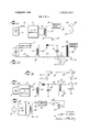
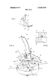
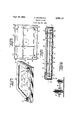
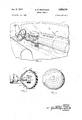
Representative patent drawing for Weapon for immobilization and capture (US 3803463)
Representative figure · US 3803463All figures on Google Patents →
Weapon for immobilization and …(Primary claim)consumer electronicsautomotivesecurity

Schematic visualization of the patent's claim structure. Hand-drawn diagrams in progress for each landmark patent.

Where you've seen this

Real-world examples

01

TASER conducted energy weapons

02

Stun guns (though often require direct contact)

03

Early prototypes of less-lethal projectile devices

Why it matters

The bigger picture

This patent is an early example of less-lethal weapon technology, specifically the electro-muscular disruption (EMD) device. It laid groundwork for devices that would later become widely used by law enforcement for crowd control and apprehension, aiming to incapacitate without causing fatal injury.

Filed

July 10, 1972

Granted

April 9, 1974

Market context

Who's building on this

Companies in this space

Axon (formerly TASER International) is the primary company that commercialized and continues to develop projectile-based conducted energy weapons, building on the foundational concepts described in this patent and subsequent advancements.

Market impact

This patent represents an early step in the development of the less-lethal weapons market. It helped establish the concept of remote electrical incapacitation, paving the way for devices that are now standard issue for many law enforcement agencies globally, significantly impacting policing tactics and public safety.

Claim 1 — Plain English

What this patent covers

This patent details a weapon system designed to subdue targets using electricity. It involves a launcher that fires projectiles, like pellets or nets, connected by thin, conductive wires to a power source. When the projectile hits a target, the wires establish an electrical path. The weapon then delivers a high-voltage, low-capacitance electrical discharge in brief pulses. This shock is intended to immobilize the target. The patent specifies delivering over 0.001 joules at voltages greater than 20 KV, with a specific capacitance-voltage product (CV) limit to ensure energy transfer. Some embodiments include a net assembly to entangle the target and ensure good contact.

The clever bit

The innovation lies in using lightweight projectiles to deploy conductive wires to a remote target, creating an electrical path for a high-voltage, low-capacitance discharge that can bridge insulative gaps and deliver incapacitating energy.

What it does not cover

  • Weapons that deliver continuous electrical current instead of discrete impulses.
  • Electrical discharges with a capacitance-voltage product (CV) higher than 10^2 volt-farads.
  • Electrical impulses delivered at voltages below 20 KV.
  • Weapons that require direct physical contact for electrical delivery, without projectiles.
  • Systems that deliver less than 0.001 joules of energy.

Patent timeline

Filing

Application submitted to the patent office

Publication

Application published, typically 18 months after filing

Grant

Patent officially issued

Expiration

Patent enters public domain

This patent is in the public domain

See the Freedom to Build guide — what is free to use, what is not, and how to cite this patent.

View guide →

PatentBrief Score

Impact Score

Strong

Citation count

40/40

Highly cited

Claim breadth

20/20

Very broad protection

Recency

0/20

Older than 20 years

Assignee scale

0/20

Independent or smaller assigneeassigneeThe entity that owns the patent — usually the inventor's employer or a company.Read more →

PatentBrief Impact Score — based on citation count, claim breadth, recency, and assignee scale. Not a legal assessment.

Heuristic Value Estimate

What this patent might be worth

Modest

$60K$192K

Midpoint $120K · expired or expiring · industry baseline

Adjust inputs →

Heuristic only — blends forward/backward citation counts, claim scope, time remaining, litigation history, and CPC-derived industry baseline. Real valuations need a professional appraisal.

Patent Claims

0 independent claims · 1 dependent

The new use of a known combination of a power supply, conductor, and projectile for applying electrical energy through a capacitive discharge to a remote target comprising the step of providing electrical energy greater than 0.001 joules to the targer in discrete, separable impulses at a voltage greater than 20 KV, but having a capacitance-voltage product, CV, less than 10 2 volt-farads, whereby the reactive impedance of the target to the electrical energy provided permits transfer of electrical energy to the target. 2. Apparatus for applying electrical energy to a remote target comprising: power supply means for generating, electrical energy in discrete impulses, at first and second output terminals in response to an initiation signal; conductive means including a pair of elongated, flexible conductors adapted to be respectively connected to said first and second output terminals; contacting means including a pair of separate, electrode elements respectively connected to the conductors of said pair for applying electrical energy to the remote target when in close proximity thereto; and a first and second projectile respectively carrying said pair of separate electrode elements, said projectiles being adapted to be deployed to separated parts of a remote target for establishing through said electrode members an extended, electrical path through the target whereby electrical energy in excess of .001 joules can be applied through said conductors, said projectiles, and said electrode elements to a remote target. 2. applying said separated electrical impulses to a remote target whereby the voltage level is adequate to conduct energy into the target through insulative gaps and whereby the target couples to a common reference potential through substantially insulative gaps. 2. engaging the target with said projectile and conductor 3. applying electrical energy to the target in a brief interrupted substantially d.c. impulse shorter than 0.1 second duration at a voltage greater than 30 kv, whereby the voltage of the impulse is sufficient to bridge insulative gaps between the conductor and the target and between the target and a common reference potential. 3. The apparatus for applying electrical energy to a remote target of claim 2, above, further including a net assembly, insulatingly intercoupling said projectiles, whereby a relatively large area of the target can be engaged by said projectiles and said electrode elements carried thereby. 4. Apparatus adapted to be connected to a source of electrical energy for conducting electrical energy to a remote target comprising in combination: a. contacting means including an electrode element having at least one conductive point, and at least one small lightweight projectile intimately connected to said electrode element adapted to be propelled to engage a remote target; b. launching means for propelling said projectile to a remote target; and c. a single flexible, thin wire conductor electrically connected to said electrode element and to said projectile and adapted to be connected to a source of electrical energy and deployed by said propelled projectile for carrying electrical energy thereby between the source and the remote target. 5. The apparatus of claim 4, above, wherein said contacting means include at least one non-conductive elongated flexible member adapted to engage the remote target entangling the target and said contacting means. 6. The apparatus of claim 5, above, wherein said contacting means further include at least a second projectile coupled to said projectiles being connected by said non-conductive elongated flexible member, said projectiles deploying said mesh and engaging and entangling the remote target to assure that both projectiles are in operational proximity to the target. 7. The apparatus of claim 4, above, further including a second flexible, thin wire conductor electrically connected between said contacting means and the source of energy and wherein said contacting means including a second projectile and a Second electrode element carried thereby electrically, connected to said second conductor for applying electrical energy to spatially separated areas of the target. 8. The apparatus of claim 7, above, further including a non-conductive mesh connecting said projectiles for engaging and entangling propelled projectiles with the target for conducting electrical energy to spatially separated parts of the target and for retaining said electrode elements in operable electrical proximity thereto. 9. A weapon comprising: a. a self-contained source of electrical energy; b. propulsion means; c. target contacting means including at least two projectiles adapted to be deployed to a remote target by said propulsion means; and d. conductive means including at least two conductors respectively operatively interconnecting said projectiles and said electrical energy source for completing an electrical circuit through the remote target; said propulsion means being adapted to deploy said projectiles in a diverging path for engaging a relatively large area of the target. 10. The weapon of claim 9, above, wherein said projectiles are darts each having a conductive point in electrical communication with its associated said conductor, whereby electrical energy applied to each of said points will bridge insulative gaps which may separate said deployed projectiles from the target. 11. The weapon of claim 9, above, wherein said target contacting means further comprises a mesh coupled to said projectiles and adapted to be said projectiles with saidprojectiles for enveloping and entangling the remote target, assuring that said projectiles will engage the target at spatially separated areas to apply electrical energy thereto. 12. The weapon of claim 9, above, wherein said target contacting means include nonconducting filaments interconnecting said projectiles for limiting the divergence of said projectiles during deployment and for enveloping and entangling a remote target, to increase the likelihood that said projectiles will engage the target to apply electrical energy between spatially separated areas of the target. 13. For use with a weapon having a self-contained electrical energy source and a trigger means for operating the weapon, a replaceable cartridge comprising in combination: a. a cartridge body including means adapted to make electrical contact with the weapon electrical energy source and the trigger means; b. target contacting means within said body including more than one projectile each having an electrode element for applying electrical energy between the weapon electrical energy source and a remote target, said projectiles being positioned to be divergently deployed; c. conducting means within said body including a separate elongated, flexible, filamentary conductor coupled to each projectile, electrically connecting said electrode elements to said electrical contact means, said conductor being of length sufficient to apply electrical energy to a remote target from the weapon; and d. pyrotechnic deploying means within said body, connected to be energized by the trigger means for deploying said projectiles and conductors to the remote target at spatially separated points, upon operation of the trigger means. 14. The replaceable cartridge of claim 13, above, wherein said target contacting means include nonconductive filaments interconnecting said projectiles for limiting the divergence of said projectiles when deployed and for enveloping and entangling the remote target. 15. For use with a weapon having a self-contained electrical energy source and a trigger means for operating the weapon, a replaceable cartridge comprising in combination: a. a cartridge body including means adapted to make electrical contact with the weapon electrical energy source and the trigger means; b. target contacting means within said body including at least a projectile having an electrode element for applying electrical energY between the weapon electrical energy source and a remote target; c. conducting means within said body including at least a single elongated, flexible, filamentary conductor connecting said projectile and electrode element to said electrical contact means, said conductor being of length sufficient to apply electrical energy to a remote target; and d. deploying means within said cartridge body connected to be energized by the trigger means for deploying said projectile and conductor to the remote target upon operation of the trigger means. 16. The process of immobilizing a remote, living target comprising the steps of: 17. The process of claim 16, above, further including the steps of repeating the energy applying step at a rate between 3 and 10 repeats per second, and shortening the duration of the individual impulses to intervals of 10 microseconds and less whereby the average power delivered to the target is approximately 2.5 watts. 18. The process of using a power supply, a conductor and a projectile for electrically coupling a remote target to the power supply comprising the steps of 19. The process of claim 18, above, wherein said applying step utilizes single conductor between the power supply and the remote target. 20. The process of claim 18, above, further including the step of generating additional electrical impulses at a rate of from 3-10 per second for application to the remote target. 21. The apparatus for applying electrical energy to a remote target of claim 2, above, wherein said conductive means are initially stored in said target contacting means. 22. The weapon of claim 9, above, wherein said target contacting means further comprises at least one nonconductive elongated flexible member interconnecting said projectiles and adapted to be deployed with said projectiles for enveloping and entangling the remote target and assuring that both projectiles will engage the target. 23. The weapon of claim 9, above, wherein said contacting means further comprises a plurality of non-conducting filaments interconnecting said projectiles, said filaments limiting the divergence of said projectiles during deployment and enveloping and entangling the remote target to increase the probability that both projectiles will engage the target.

Claims are the legal boundaries of the patent. An independent claim stands alone. A dependent claim adds limitations to its parent, narrowing — but not broadening — the scope.

The original legal language

Original claims

37 claims as filed with the patent office.

Concepts involved

ClaimPrior artNon-obviousnessNoveltySpecificationAssigneePatent term

Citations

Patent lineage

Cited by later patents

152

later patents that build on this invention

View patents →

Cite this patent

Cover, J. (1974). Weapon That Shoots Wires to Deliver Electric Shocks (U.S. Patent No. 3,803,463). U.S. Patent and Trademark Office. https://patentbrief.org/patent/us/3803463/taser-stun-gun-cover

Auto-generated from the patent record. Double-check author order and the issue date against the official USPTO document before submitting.

Embed

Add this patent to your site

Drop this plain-English patent card into any blog post or article — free, no signup. It always links back to the full breakdown here.

<div data-patentlens-widget data-patent-number="US3803463"></div>
<script src="https://patentbrief.org/embed.js" async></script>

Stay in the loop

Get a weekly digest of new patents.

One email per week. No spam. Unsubscribe anytime.

Keep exploring

Related patents you should know

US 4683195 · 1987

How to Make Billions of Copies of a DNA Segment

This patent describes the Polymerase Chain Reaction (PCR), a method to rapidly create many copies of a specific piece of DNA or RNA, enabling its detection and analysis.

Cetus Corp

US 8697359 · 2014

How to Edit Genes in Human Cells Using an Engineered CRISPR System

This patent describes an engineered CRISPR-Cas9 system for precisely cutting DNA in eukaryotic cells to change how genes work, opening the door for gene editing in complex organisms.

Massachusetts Institute of Technology

US 7657849 · 2010

How the iPhone's Slide-to-Unlock Gesture Works

Apple's 2010 patent describes unlocking a device by dragging a specific graphical image across the touchscreen along a predefined path, a gesture that became iconic with the original iPhone.

Apple Inc

US 4733665 · 1988

How Doctors Implant a Permanent Stent Using a Balloon

This patent describes the method for placing a permanent, expandable wire mesh tube inside a blood vessel or other body tube using a balloon-tipped catheter to widen it and keep it open.

Expandable Grafts Partnership

US 4965188 · 1990

How to Make Many Copies of a DNA Piece with Heat

This patent describes the Polymerase Chain Reaction (PCR) method, a technique to make millions of copies of a specific DNA segment using a heat-resistant enzyme and repeated temperature changes.

Cetus Corp

US 4235871 · 1980

How to Encapsulate Active Materials in Lipid Bubbles Efficiently

This patent describes a method for trapping biologically active substances inside tiny, multi-layered fat bubbles called liposomes, using a specific water-in-oil emulsion and gel-forming process to improve how much material gets captured.

Individual

Semantically similar

You might also find these interesting

SEARCH ALL

More to explore

More in Consumer Electronics
Browse all Consumer Electronics

New to patents?

What is a patent?How to read a patentAnatomy of a claimHow strong is this patent?What the citations meanWhat it doesn't coverConsumer Electronics PatentsPatent glossary
Explore the landscape:consumer electronics patents →automotive patents →security patents →

Common Questions

Frequently Asked Questions

What does Weapon That Shoots Wires to Deliver Electric Shocks cover?

This 1974 patent describes a weapon that fires projectiles carrying wires to deliver incapacitating electric shocks to a target from a distance.

Who owns patent US 3803463?

Individual owns this patent, granted in 1974.

When does this patent expire?

This patent has expired and is now in the public domain — anyone can use the invention freely.

What is patent US 3803463 cited by?

This patent has been cited by 152 later patents that build on its ideas.

What problem does this patent solve?

This patent is an early example of less-lethal weapon technology, specifically the electro-muscular disruption (EMD) device. It laid groundwork for devices that would later become widely used by law enforcement for crowd control and apprehension, aiming to incapacitate without causing fatal injury.

What does this patent NOT cover?

Weapons that deliver continuous electrical current instead of discrete impulses.

Same assignee

More from Individual

View all →
US 12442345·2025

How an Auxiliary Controller Manages Supplemental Fuel Injection

US 12409012·2025

A Modular Dental Tool for Holding Back Lips, Cheeks, and Tongue

US 12327854·2025

Capturing Carbon Dioxide While Making Electricity with Hydrogen and Solar

US 12233456·2025

How to Improve 3D Printing Using Cold Spray Metal Deposition

Patent monitoring

Get notified when new matching patents are published

Get notified when this company files a new patent. Weekly digest · Confirm via email · Unsubscribe anytime.

Last reviewed: June 13, 2026 · PatentBrief is not a law firm and this is not legal advice.