How Vacuum Tubes Detect Tiny Changes in High-Resistance Sensors
A 1973 circuit design using a vacuum tube to detect microscopic resistance shifts in sensors like ionization chambers, commonly used in early smoke detectors.
Original patent title: “Circuit for detection of small resistance changes in ionization chamber devices”
A 1973 circuit design using a vacuum tube to detect microscopic resistance shifts in sensors like ionization chambers, commonly used in early smoke detectors. Granted to Central Investment Corp in 1973 with 5 claims and 2 forward citations, and it is now in the public domain.
Coverage
What does this patent actually cover?
This patent describes an electronic circuit designed to monitor high-resistance sensors, such as ionization chambers, by using a vacuum tube as a sensitive switch. The circuit biases the tube's control grid so that it is always conducting a small, steady amount of current, which allows it to detect even tiny fluctuations in the resistance of the connected sensor. When the sensor's resistance changes—perhaps due to smoke particles entering an ionization chamber—the circuit triggers a relay. It also incorporates positive feedback to ensure that once a threshold is reached, the switch activates decisively rather than flickering.
The gap
What does this patent NOT cover?
- Does not cover modern solid-state sensors that use transistors or microcontrollers instead of vacuum tubes.
- Does not cover digital signal processing methods for detecting resistance changes.
- Does not cover circuits that do not maintain a constant flow of grid current during operation.
These exclusions are unique to PatentBrief — derived from the actual claim language, not patent-office boilerplate.
Key facts
What made this novel
The circuit forces the vacuum tube to operate in a state where grid current is always flowing, effectively turning the tube into a high-impedance bridge that matches the resistance of the sensor itself.
The Patent Drawing
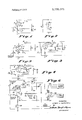
Schematic visualization of the patent's claim structure. Hand-drawn diagrams in progress for each landmark patent.
Where you've seen this
Real-world examples
Early electronic smoke detectors
Industrial ionization-based gas leak sensors
Why it matters
The bigger picture
This technology was foundational for the development of early electronic smoke and fire detection systems. By allowing a simple vacuum tube to act as a high-gain amplifier for extremely weak electrical signals, it enabled reliable, automated monitoring of environmental conditions before modern integrated circuits became affordable.
Filed
December 4, 1969
Granted
May 22, 1973
Market context
Who's building on this
Companies in this space
While the specific vacuum tube technology is largely obsolete, the principles of high-impedance sensing are now implemented by companies like Honeywell and Siemens using modern CMOS (Complementary Metal-Oxide-Semiconductor) sensors.
Market impact
This patent represents a period where industrial safety systems transitioned from mechanical or simple bimetallic switches to electronic monitoring. It helped define the architecture for ionization-based fire detection, which became a standard safety requirement in residential and commercial buildings for decades.
Claim 1 — Plain English
What this patent covers
This patent describes an electronic circuit designed to monitor high-resistance sensors, such as ionization chambers, by using a vacuum tube as a sensitive switch. The circuit biases the tube's control grid so that it is always conducting a small, steady amount of current, which allows it to detect even tiny fluctuations in the resistance of the connected sensor. When the sensor's resistance changes—perhaps due to smoke particles entering an ionization chamber—the circuit triggers a relay. It also incorporates positive feedback to ensure that once a threshold is reached, the switch activates decisively rather than flickering.
The clever bit
The circuit forces the vacuum tube to operate in a state where grid current is always flowing, effectively turning the tube into a high-impedance bridge that matches the resistance of the sensor itself.
What it does not cover
- Does not cover modern solid-state sensors that use transistors or microcontrollers instead of vacuum tubes.
- Does not cover digital signal processing methods for detecting resistance changes.
- Does not cover circuits that do not maintain a constant flow of grid current during operation.
Patent timeline
Application submitted to the patent office
Application published, typically 18 months after filing
Patent officially issued
Patent enters public domain
This patent is in the public domain
See the Freedom to Build guide — what is free to use, what is not, and how to cite this patent.
PatentBrief Score
Impact Score
Limited data
Citation count
10/40
Early citations
Claim breadth
3/20
Moderate scope
Recency
0/20
Older than 20 years
Assignee scale
0/20
Independent or smaller assigneeassigneeThe entity that owns the patent — usually the inventor's employer or a company.Read more →
PatentBrief Impact Score — based on citation count, claim breadth, recency, and assignee scale. Not a legal assessment.
Heuristic Value Estimate
What this patent might be worth
$5K – $14K
Midpoint $9K · expired or expiring · industry ×1.5
Heuristic only — blends forward/backward citation counts, claim scope, time remaining, litigation history, and CPC-derived industry baseline. Real valuations need a professional appraisal.
Patent Claims
0 independent claims · 1 dependent
Claims are the legal boundaries of the patent. An independent claim stands alone. A dependent claim adds limitations to its parent, narrowing — but not broadening — the scope.
The original legal language
Original claims
5 claims as filed with the patent office.
Concepts involved
Citations
Patent lineage
Cite this patent
Blackwell, L. (1973). How Vacuum Tubes Detect Tiny Changes in High-Resistance Sensors (U.S. Patent No. 3,735,375). U.S. Patent and Trademark Office. https://patentbrief.org/patent/us/3735375/smoke-detector-ionization
Auto-generated from the patent record. Double-check author order and the issue date against the official USPTO document before submitting.
Embed
Add this patent to your site
Drop this plain-English patent card into any blog post or article — free, no signup. It always links back to the full breakdown here.
<div data-patentlens-widget data-patent-number="US3735375"></div>
<script src="https://patentbrief.org/embed.js" async></script>
Stay in the loop
Get a weekly digest of new patents.
One email per week. No spam. Unsubscribe anytime.
Keep exploring
Related patents you should know
US 4683195 · 1987
How to Make Billions of Copies of a DNA Segment
This patent describes the Polymerase Chain Reaction (PCR), a method to rapidly create many copies of a specific piece of DNA or RNA, enabling its detection and analysis.
Cetus Corp
US 8697359 · 2014
How to Edit Genes in Human Cells Using an Engineered CRISPR System
This patent describes an engineered CRISPR-Cas9 system for precisely cutting DNA in eukaryotic cells to change how genes work, opening the door for gene editing in complex organisms.
Massachusetts Institute of Technology
US 7657849 · 2010
How the iPhone's Slide-to-Unlock Gesture Works
Apple's 2010 patent describes unlocking a device by dragging a specific graphical image across the touchscreen along a predefined path, a gesture that became iconic with the original iPhone.
Apple Inc
US 4733665 · 1988
How Doctors Implant a Permanent Stent Using a Balloon
This patent describes the method for placing a permanent, expandable wire mesh tube inside a blood vessel or other body tube using a balloon-tipped catheter to widen it and keep it open.
Expandable Grafts Partnership
US 4965188 · 1990
How to Make Many Copies of a DNA Piece with Heat
This patent describes the Polymerase Chain Reaction (PCR) method, a technique to make millions of copies of a specific DNA segment using a heat-resistant enzyme and repeated temperature changes.
Cetus Corp
US 4235871 · 1980
How to Encapsulate Active Materials in Lipid Bubbles Efficiently
This patent describes a method for trapping biologically active substances inside tiny, multi-layered fat bubbles called liposomes, using a specific water-in-oil emulsion and gel-forming process to improve how much material gets captured.
Individual
Semantically similar
You might also find these interesting
US 2485586 · 1949 · International Standard Electric Corp
How the Geiger Counter Detects Invisible Radiation
US 2524035 · 1950 · Bell Telephone Laboratories Inc
The Invention of the Transistor
US 2058761 · 1936 · Arnold O. Beckman
How Arnold Beckman Invented the Modern pH Meter
US 1203495 · 1916 · General Electric Co
How William Coolidge Invented the Modern X-Ray Tube
More to explore
More in Consumer Electronics
US 7657849 · 2010 · Apple Inc
How the iPhone's Slide-to-Unlock Gesture Works
US 7479949 · 2009 · Apple Inc
How Touchscreens Understand Your Finger Swipes and Scrolls
US 4528643 · 1985 · FPDC Inc
How Stores Make Custom Products On-Demand with Remote Approval
US 7469381 · 2008 · Apple Inc
How Touchscreens Show and Snap Back When You Scroll Past an Edge
New to patents?
Common Questions
Frequently Asked Questions
What does How Vacuum Tubes Detect Tiny Changes in High-Resistance Sensors cover?
A 1973 circuit design using a vacuum tube to detect microscopic resistance shifts in sensors like ionization chambers, commonly used in early smoke detectors.
Who owns patent US 3735375?
Central Investment Corp owns this patent, granted in 1973.
When does this patent expire?
This patent has expired and is now in the public domain — anyone can use the invention freely.
What is patent US 3735375 cited by?
This patent has been cited by 2 later patents that build on its ideas.
What problem does this patent solve?
This technology was foundational for the development of early electronic smoke and fire detection systems. By allowing a simple vacuum tube to act as a high-gain amplifier for extremely weak electrical signals, it enabled reliable, automated monitoring of environmental conditions before modern integrated circuits became affordable.
What does this patent NOT cover?
Does not cover modern solid-state sensors that use transistors or microcontrollers instead of vacuum tubes.
Patent monitoring