How a Carbon Capture Container Traps CO2 from Air
This patent describes a specialized container design for direct air capture that efficiently channels air through a CO2-absorbing material using a perforated inner structure and specific fluid flow paths.
Original patent title: “System and method for improving the performance and lowering the cost of atmospheric carbon dioxide removal by direct air capture”
This patent describes a specialized container design for direct air capture that efficiently channels air through a CO2-absorbing material using a perforated inner structure and specific fluid flow paths. Granted to Air to Earth Holdings in 2024 with 26 claims, and it is expected to expire in 2043.
Coverage
What does this patent actually cover?
The patent describes a carbon capture vessel designed to efficiently remove carbon dioxide from a fluid like air. It features an "outer container" and, nestled inside it, a "sorbent subcontainer" (ClaimclaimA numbered sentence at the end of a patent that legally defines what the inventor owns. The most important section.Read more → 1). A "gap" exists between these two containers. The inner "sorbent subcontainer" has "perforations" (small holes) in its sidewall, allowing fluid to pass through. A "sorbent material," which absorbs CO2, is placed either inside this subcontainer or right next to its perforated sidewall (Claim 1). The design guides the fluid flow: it enters the subcontainer in a "first direction," then gets redirected to flow "orthogonal" (at a right angle) through the sorbent material in a "second direction," before returning to the "first direction" (Claim 3). For example, air might enter from the top, flow sideways through the sorbent, and then exit downwards along the exterior of the inner subcontainer (Claim 4). The entire vessel can also be "selectively sealable" (Claim 1).
The gap
What does this patent NOT cover?
- Does not cover carbon capture systems that do not use an inner "sorbent subcontainer" with perforations in its sidewall.
- Does not cover vessels where the fluid flow through the sorbent material is not redirected at an "orthogonal" angle to the initial flow direction.
- Does not cover the larger system components like multiple fans, air diverters, or velocity stacks that move air into and out of the containers, as these are not claimed in the provided text.
- Does not cover carbon capture designs where the sorbent material is not housed within an "annulus" formed by an outer tube around the perforated subcontainer (for claimsclaimsThe numbered statements at the end of a patent that legally define what the inventor owns.Read more → 6, 8, 9).
- Does not cover systems that do not involve a "gap" between an outer container and an inner sorbent subcontainer.
These exclusions are unique to PatentBrief — derived from the actual claim language, not patent-office boilerplate.
Key facts
What made this novel
The cleverness lies in the specific, multi-layered container design with perforations and the precisely defined fluid flow path. By forcing the fluid to enter in one direction, then redirecting it orthogonally through the sorbent material, and finally returning it, the design ensures efficient and uniform contact with the sorbent, maximizing CO2 capture within a compact vessel. The "gap" and "selectively sealable" aspects further suggest optimized regeneration or maintenance.
The Patent Drawing
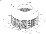
Schematic visualization of the patent's claim structure. Hand-drawn diagrams in progress for each landmark patent.
Where you've seen this
Real-world examples
Climeworks direct air capture plants
Carbon Engineering facilities
Global Thermostat DAC technology
Other direct air capture (DAC) systems
Why it matters
The bigger picture
Direct Air Capture (DAC) technology is crucial for removing existing carbon dioxide from the atmosphere, which is vital for combating climate change. This patent aims to improve the efficiency and lower the cost of such systems by optimizing the design of the individual capture vessels. By precisely controlling how air flows through the CO2-absorbing material, it seeks to maximize contact and absorption, making the overall process more effective and economically viable. This kind of engineering innovation is essential for scaling up DAC to a meaningful level.
Filed
December 22, 2023
Granted
October 22, 2024
Market context
Who's building on this
Companies in this space
Companies like Climeworks, Carbon Engineering, and Global Thermostat are leading the development and deployment of direct air capture technologies. Air to Earth Holdings, the assigneeassigneeThe entity that owns the patent — usually the inventor's employer or a company.Read more →, is actively working on improving the performance and cost-effectiveness of these systems, building on innovations like the one described in this patent. Other startups and research institutions are also heavily invested in optimizing DAC components.
Market impact
This patent contributes to the ongoing effort to make direct air capture more efficient and affordable. By refining the design of the core capture vessels, it can help reduce the energy and material costs associated with removing CO2 from the atmosphere. Such improvements are critical for scaling DAC technology to a point where it can significantly impact global carbon emissions, potentially enabling new project deployments and attracting further investment into the nascent DAC industry.
Claim 1 — Plain English
What this patent covers
The patent describes a carbon capture vessel designed to efficiently remove carbon dioxide from a fluid like air. It features an "outer container" and, nestled inside it, a "sorbent subcontainer" (Claim 1). A "gap" exists between these two containers. The inner "sorbent subcontainer" has "perforations" (small holes) in its sidewall, allowing fluid to pass through. A "sorbent material," which absorbs CO2, is placed either inside this subcontainer or right next to its perforated sidewall (Claim 1). The design guides the fluid flow: it enters the subcontainer in a "first direction," then gets redirected to flow "orthogonal" (at a right angle) through the sorbent material in a "second direction," before returning to the "first direction" (Claim 3). For example, air might enter from the top, flow sideways through the sorbent, and then exit downwards along the exterior of the inner subcontainer (Claim 4). The entire vessel can also be "selectively sealable" (Claim 1).
The clever bit
The cleverness lies in the specific, multi-layered container design with perforations and the precisely defined fluid flow path. By forcing the fluid to enter in one direction, then redirecting it orthogonally through the sorbent material, and finally returning it, the design ensures efficient and uniform contact with the sorbent, maximizing CO2 capture within a compact vessel. The "gap" and "selectively sealable" aspects further suggest optimized regeneration or maintenance.
What it does not cover
- Does not cover carbon capture systems that do not use an inner "sorbent subcontainer" with perforations in its sidewall.
- Does not cover vessels where the fluid flow through the sorbent material is not redirected at an "orthogonal" angle to the initial flow direction.
- Does not cover the larger system components like multiple fans, air diverters, or velocity stacks that move air into and out of the containers, as these are not claimed in the provided text.
- Does not cover carbon capture designs where the sorbent material is not housed within an "annulus" formed by an outer tube around the perforated subcontainer (for claims 6, 8, 9).
- Does not cover systems that do not involve a "gap" between an outer container and an inner sorbent subcontainer.
Patent timeline
Application submitted to the patent office
Application published, typically 18 months after filing
Patent officially issued
Patent enters public domain
PatentBrief Score
Impact Score
Early stage
Citation count
0/40
No citations yet
Claim breadth
17/20
Very broad protection
Recency
20/20
Granted within 5 years
Assignee scale
0/20
Independent or smaller assigneeassigneeThe entity that owns the patent — usually the inventor's employer or a company.Read more →
PatentBrief Impact Score — based on citation count, claim breadth, recency, and assignee scale. Not a legal assessment.
Heuristic Value Estimate
What this patent might be worth
$26K – $84K
Midpoint $53K · 17.1 yr remaining · industry ×0.9
Heuristic only — blends forward/backward citation counts, claim scope, time remaining, litigation history, and CPC-derived industry baseline. Real valuations need a professional appraisal.
Claim text not yet imported for this patent
The original legal language
Original claims
26 claims as filed with the patent office.
Concepts involved
Citations
Patent lineage
Cite this patent
Jr., J. J. S. (2024). How a Carbon Capture Container Traps CO2 from Air (U.S. Patent No. 12,121,848). U.S. Patent and Trademark Office. https://patentbrief.org/patent/us/12121848/system-and-method-for-improving-the-performance-and-lowering-the-cost-of-atmosph-12121848
Auto-generated from the patent record. Double-check author order and the issue date against the official USPTO document before submitting.
Embed
Add this patent to your site
Drop this plain-English patent card into any blog post or article — free, no signup. It always links back to the full breakdown here.
<div data-patentlens-widget data-patent-number="US12121848"></div>
<script src="https://patentbrief.org/embed.js" async></script>
Stay in the loop
Get a weekly digest of new patents.
One email per week. No spam. Unsubscribe anytime.
Keep exploring
Related patents you should know
US 4683195 · 1987
How to Make Billions of Copies of a DNA Segment
This patent describes the Polymerase Chain Reaction (PCR), a method to rapidly create many copies of a specific piece of DNA or RNA, enabling its detection and analysis.
Cetus Corp
US 8697359 · 2014
How to Edit Genes in Human Cells Using an Engineered CRISPR System
This patent describes an engineered CRISPR-Cas9 system for precisely cutting DNA in eukaryotic cells to change how genes work, opening the door for gene editing in complex organisms.
Massachusetts Institute of Technology
US 7657849 · 2010
How the iPhone's Slide-to-Unlock Gesture Works
Apple's 2010 patent describes unlocking a device by dragging a specific graphical image across the touchscreen along a predefined path, a gesture that became iconic with the original iPhone.
Apple Inc
US 4733665 · 1988
How Doctors Implant a Permanent Stent Using a Balloon
This patent describes the method for placing a permanent, expandable wire mesh tube inside a blood vessel or other body tube using a balloon-tipped catheter to widen it and keep it open.
Expandable Grafts Partnership
US 4965188 · 1990
How to Make Many Copies of a DNA Piece with Heat
This patent describes the Polymerase Chain Reaction (PCR) method, a technique to make millions of copies of a specific DNA segment using a heat-resistant enzyme and repeated temperature changes.
Cetus Corp
US 4235871 · 1980
How to Encapsulate Active Materials in Lipid Bubbles Efficiently
This patent describes a method for trapping biologically active substances inside tiny, multi-layered fat bubbles called liposomes, using a specific water-in-oil emulsion and gel-forming process to improve how much material gets captured.
Individual
Semantically similar
You might also find these interesting
US 11266943 · 2022
How a System Captures Carbon Dioxide from the Air More Efficiently
US 11648507 · 2023 · Zero Carbon Energy Innovation Union
How to Capture Carbon Dioxide from Air or Smoke Using Seawater
US 20220203297 · 8 Rivers Capital
Capturing Carbon Dioxide While Making Industrial Materials
US 11325075 · 2022 · Singapore University of Technology and Design
Two-Layer Membrane with Tiny, Ordered Pores for Carbon Capture
More to explore
More in Energy & Clean Tech
US RE49155 · 2022 · Halliburton Energy Services Inc
Electric or Natural Gas Blending and Pumping for Oil Wells
US 11436484 · 2022 · Nvidia Corp
Nvidia's Method for Training Self-Driving Car AI in Simulations
US 11840398 · 2023 · Titan Trailers Inc
How Titan Trailers Builds Stronger, Smoother Cargo Containers
US 2708656 · 1955
How the First Nuclear Reactor Works
New to patents?
Common Questions
Frequently Asked Questions
What does How a Carbon Capture Container Traps CO2 from Air cover?
This patent describes a specialized container design for direct air capture that efficiently channels air through a CO2-absorbing material using a perforated inner structure and specific fluid flow paths.
Who owns patent US 12121848?
Air to Earth Holdings owns this patent, granted in 2024.
When does this patent expire?
This patent is expected to expire on December 22, 2043, when the invention enters the public domain.
What problem does this patent solve?
Direct Air Capture (DAC) technology is crucial for removing existing carbon dioxide from the atmosphere, which is vital for combating climate change. This patent aims to improve the efficiency and lower the cost of such systems by optimizing the design of the individual capture vessels. By precisely controlling how air flows through the CO2-absorbing material, it seeks to maximize contact and absorption, making the overall process more effective and economically viable. This kind of engineering innovation is essential for scaling up DAC to a meaningful level.
What does this patent NOT cover?
Does not cover carbon capture systems that do not use an inner "sorbent subcontainer" with perforations in its sidewall.
Patent monitoring